
Product search
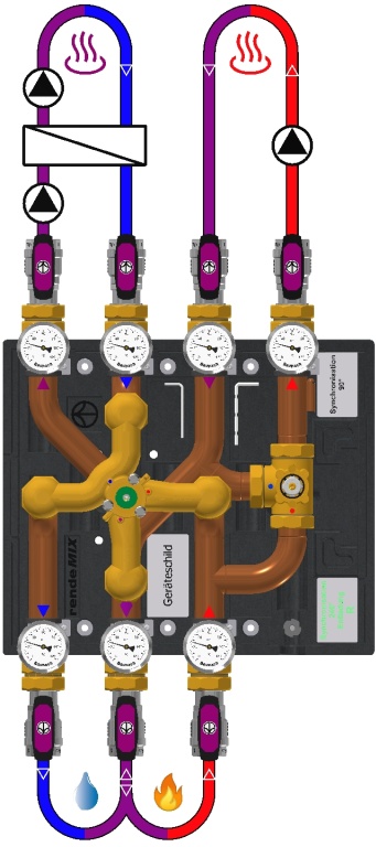
rSYS DN25s 3x4+3mix L
Accessories needed
|
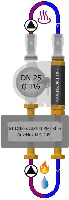
ST DN25s AD100 P60 RL 5001139 |
|
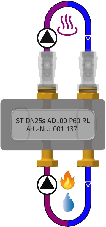
ST DN25s AD100 P60 RL001137 |
Recommended accessories
|
|
ISO KuHV DN25s G1½(i)xRp1996085 |
Configure product variant
Nominal width
Performance class
Kvs = 13.3 • V'max[100mbar] = 4.2m³/h
Q'max[20K] = 98kW
2nd mixing circuit (LT) for ST on-site:
Kvs = 9.7 • V'max[100mbar] = 3.1m³/h
Q'max[10K] = 36kW
Flow direction producer
Pump flange
Product documentation
Assembly instructions
Assembly instructions: For specialist partners only.
Please log in here or register here
Actuator multi-way mixer: For specialist partners only.
Please log in here or register here
Actuator three-way mixer: For specialist partners only.
Please log in here or register here
Spare parts drawing
Spare parts drawing For specialist partners only.
Please log in here or register here
Data sheet
Tender text
Baunach article master data Version: 22.11.23
BAFA funding opportunity as part of heating system optimisation through hydraulic balancing and installation of separate control technology
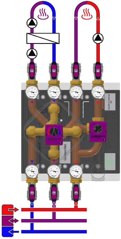
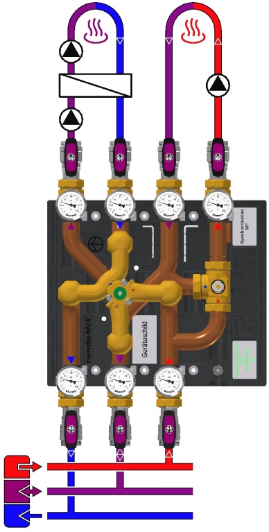
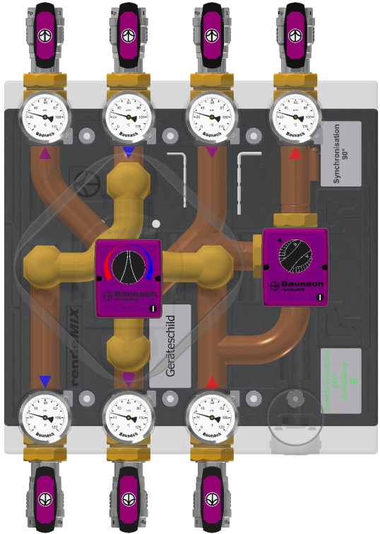
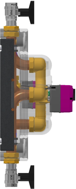
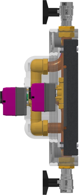
rendeMIX Mehrwege-Mischverteiler mit 3/2-Wege-Tangential-Mischhahn DN25×G1½(a) MsGuss (Adapter grün) und 3-Wege-Mischhahn DN32×G1½(a) Ms58, Küken und Deckel Ms58
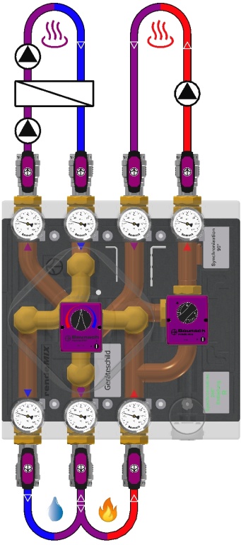
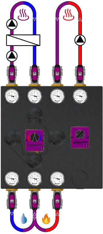
For highly efficient two-zone unloading of a buffer tank in a mixed low-temperature circuit (2nd mixing circuit) by means of highly efficient operation of a system separation via flow control with highly efficient use of the return flow of a mixed high-temperature circuit (1st mixing circuit).
1st mixing circuit: EMS 90-3P actuator, 230V~ 50Hz 3.5VA 3-point signal, 5Nm (240h), 90°, 70s, grey adapter. 2nd mixing circuit: EMS 240 actuator, 230V~ 50Hz 3.5VA 3-point signal, 5Nm (240h), 240°, 93s
Two-circuit manifold assembly with 3 connections to the heat generator (buffer or boiler with flue gas heat exchanger), CuØ35×1, pipe spacing 100mm, DN32×G1½(a) flat
3 integrated gravity brakes/backflow preventer, Dp10mbar
1st mixing circuit (HT): Kvs = 13.3 - V'max[100mbar] = 4.2m³/h - Q'max[20K] = 98kW - leakage rate < 0,1% - 2. Mischkreis (NT) für Systemtrennung bauseits: Kvs = 9,7 • V'max[100mbar] = 3,1m³/h • Q'max[10K] = 36kW • Leckrate < 0,1%
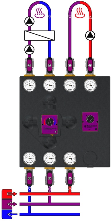
7 Thermometer 0-120°C, Ø63mm, soldering sleeves Ms58
7 Ball valve screw connections, DN25s passage, PN20, G1½(i)×Rp1 flat-sealing, stuffing box, spindle with aluminium T-handle
Insulating moulded tray EPP 40g/l, black, 450×450mm, quick assembly kit
Without pump flanges
Assembly does NOT include pump compensator - PAS L180 (Part No.: 001 338)
Assembly does not contain a pump
Model DN 25 - strong version, PN 10bar, Tmax 120°C
ATTENTION: CANNOT BE USED WITHOUT SYSTEM SEPARATION!
Performance data
1st mixing circuit (HT): Kvs = 13.3 - V'max[100mbar] = 4.2m³/h - Q'max[20K] = 98kW - leakage rate < 0,1% - 2. Mischkreis (NT) für Systemtrennung bauseits: Kvs = 9,7 • V'max[100mbar] = 3,1m³/h • Q'max[10K] = 36kW • Leckrate < 0,1%