
Product search


rSYS DN25s 2x4 RH 15
Accessories needed
|
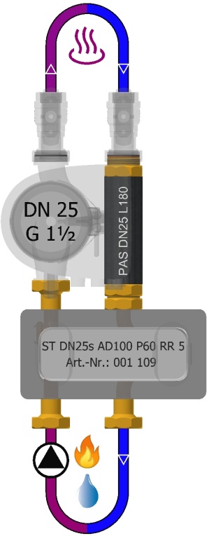
ST DN25s AD100 P60 RR 5001109 |
|
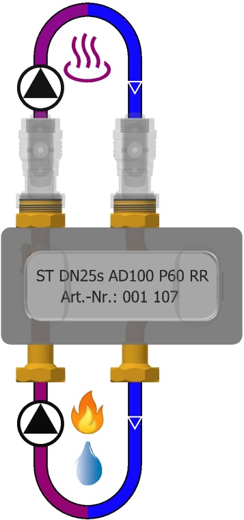
ST DN25s AD100 P60 RR001107 |
Recommended accessories
|
DÜV DN15 2x2 MUL-Set R001345 |
|
|
ISO KuHV DN25s G1½(i)xRp1996085 |
Further questions?
Contact technical supportConfigure product variant
Nominal width
Performance class
Kvs = 11.9 • V'max[100mbar] = 3.8m³/h
Q'max[20K] = 88kW
Mixing circuit (LT) with ST DN25s: Kvs = 7.2 • V'max[100mbar] = 2.3m³/h
Q'max[10K] = 27kW
Flow direction producer
Pump flange
Product documentation
Assembly instructions
Assembly instructions: For specialist partners only.
Please log in here or register here
Actuator multi-way mixer: For specialist partners only.
Please log in here or register here
Spare parts drawing
Spare parts drawing For specialist partners only.
Please log in here or register here
Data sheet
GAEB
Tender text
Baunach article master data Version: 19.11.24
BAFA funding opportunity as part of heating system optimisation through hydraulic balancing and installation of separate control technology
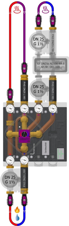
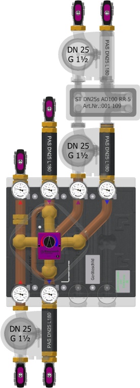
rendeMIX multi-port mixing manifold with 3/2-way tangential mixing valve DN25×G1½(a) MsGuss (adapter green), plug and cover Ms58
For highly efficient utilisation of the return flow of an unmixed high-temperature circuit in a mixed low-temperature circuit by means of highly efficient operation of a system separation via flow control at a condensing boiler, a stratified storage tank or a heat transfer station.
Actuator EMS 240, 230V~ 50Hz 3.5VA 3-point signal, 5Nm (240h), 240°, 93s
Dual circuit manifold assembly with 2 connections to the heat source and 4 connections to the heat sinks, CuØ35×1, DN32×G1½(a) flat, pipe spacing 100mm.
3 integrated gravity brakes/backflow preventer, Dp10mbar
Direct heating circuit (HT): Kvs = 11.9 - V'max[100mbar] = 3.8m³/h - Q'max[20K] = 88kW - Mixed circuit (LT) with ST DN25s: Kvs = 7.2 - V'max[100mbar] = 2.3m³/h - Q'max[10K] = 27kW - Leakage rate < 0,1%
6 Thermometers 0-120°C, Ø63mm, soldering sleeves Ms58
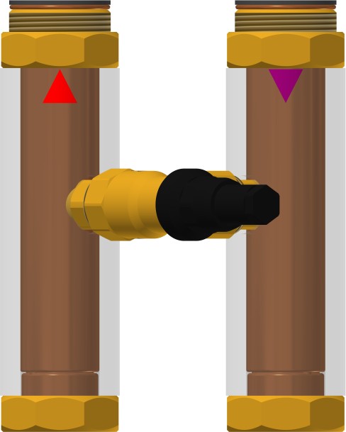
6 ball valve screw connections, DN25s passage, PN20, G1½(i)×Rp1 flat-sealing, stuffing box, spindle with aluminium T-handle
Insulating moulded tray EPP 40g/l, black, 450×450mm, quick assembly kit
With pump flanges G1½(i) for pumps DN25 at the heat generator flow (1) and mixing circuit flow (5)
Assembly contains THREE pump compensators - PAS L180 - with G1½(a)×G1½(i) fittings for compensating a pump DN25, length 180mm, insulated (part no.: 001 338).
With built-in high-efficiency Grundfos UPM3 pump, DN25, 130mm, H 5-6mWS, 230V~ 50Hz, 2m connection cable, EEI < 0,2
Model DN 25 - strong version, PN 10bar, Tmax 120°C
ATTENTION: CANNOT BE USED WITHOUT SYSTEM SEPARATION!
Performance data
Direct heating circuit (HT): Kvs = 11.9 - V'max[100mbar] = 3.8m³/h - Q'max[20K] = 88kW - Mixed circuit (LT) with ST DN25s: Kvs = 7.2 - V'max[100mbar] = 2.3m³/h - Q'max[10K] = 27kW - Leakage rate < 0,1%