System hydraulics for high CHP running time
 Heating with residual heat from the return flow
When modernising the heating system in a hotel property in Essen, the system hydraulics of the bivalent heating system were set up with a two-zone buffer management and the principle of return utilisation. This was made possible by the use of multi-way mixing manifolds for buffer charging and the supply of the heating circuits. Due to the system concept with optimised hydraulics between heat generation and distribution, the peak load boiler became a reserve heat generator, and the small CHP unit runs almost around the clock.
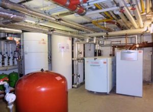
Figure 1: The CHP unit (centre) charges the two buffer tanks (left) according to the two-zone principle. The gas condensing boiler (right) used as a peak load boiler only switches on when the temperature in the upper buffer zone falls below the minimum temperature for DHW heating.
The guest house of the Kolping Vocational Training Centre Essen offers 14 double rooms, six single rooms and two flats on three floors. The hotel has its own catering kitchen. In 2009, the heating system was completely modernised. The system concept includes a small CHP unit (12.5 kWth, 4.7 kWel), a gas condensing boiler for the peak load (120 kW), two 500-litre buffer tanks connected in parallel, and a storage water heater with a capacity of 500 litres, which is charged via a stratified charging system (Figure 1).
Inform compactly
The CHP runtime is not only dependent on the potential size of the heat sink, but is also significantly influenced by the system hydraulics.
Key factors are intelligent buffer management and the lowest possible return temperature from the heat distribution.
Both functions - and additionally the return temperature increase for the CHP unit - can be easily realised with the rendeMIX multi-way mixing manifolds. The control can be carried out via standard controllers.
Different system temperatures
The three existing consumer circuits operate with different system temperatures:
- Mixed radiator heating circuit: 70/50 °C
- Mixed air heater-heating circuit for the AHU: 80/60 °C
- DHW heating: 85/60 °C
One of the main planning tasks for the heat distribution system was therefore to provide the correct flow temperature for each heating circuit. Furthermore, the usable buffer volume had to be maximised in order to achieve long CHP running times. In addition, this system concept was designed to implement the principle of return temperature utilisation: If the temperature from the return of a heating circuit is sufficient to supply another heating circuit with a lower temperature level, this heating heat should first be used before accessing the flow.
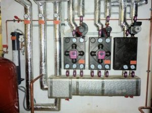
Fig. 2: For heat distribution, the multi-way mixing manifolds from HG Baunach GmbH & Co. KG were used together with a three-chamber distributor manufactured by Magra. The sequence of the distributor outlets is based on the temperature gradient in the return flow in the direction of flow to the boiler.
This was implemented with multi-way mixing manifolds of the type rendeMIX, which together with a specially developed three-chamber manifold (Fig. 2) ensure the correct system temperatures in the three heating circuits. Another multi-way mixing manifold was used as a link between the CHP unit and the buffer storage tank. Together with an integrated fixed-value controller, this fulfils the necessary return temperature increase for the CHP unit and simultaneously organises the two-zone charging of the buffer storage tank.
CHP covers heat demand almost alone
The system can be monitored remotely via the controls of the two heat generators, and the operating data and running times are also documented. About ten months after the modernisation, the operating data showed that the peak-load boiler only starts occasionally and is only used for DHW heating in the summer. On the other hand, the installed small CHP unit clearly exceeds the planned operating performance: the planning was based on an annual operating time of 7,000 h/a. In fact, however, the motor runs for more than 23 hours per year. In reality, however, the engine runs for more than 23 h/d, which corresponds to a utilisation of more than 96 % and means an extrapolated annual performance of at least 8400 h/a.
In contrast, the utilisation of the 120 kW peak load boiler is only 1.4%. This value is based on operating data for the summer months (DHW heating). However, when considered for year-round operation, it can be concluded that the operating times of the peak-load boiler and the CHP unit are in the right proportion to each other: "Due to the loading and unloading of the buffer storage tanks according to the two-zone principle, the heat load is first completely passed on to the CHP unit before the peak-load boiler starts up," explains Hans-Georg Baunach, who was responsible for the design of the system hydraulics (Fig. 3).
Building board guest house Marienstraße
Object:
- Marienstraße Guest House, 45307 Essen
Operator:
- Kolping Vocational Training Centre Essen
- Non-profit limited liability company
- www.kbbw-gaestehaus.de
Heating system:
- CHP: ecopower, 12.5 kWth / 4.7 kWel
- Gas condensing boiler: Vaillant ecocraft 120 6/3, 120 kW
- 2 buffer tanks á 500 l
- DHW cylinder: Vaillant actostore, 500 l, with stratified charging system
Hydraulic planning and multi-way mixing manifold:
- HG Baunach GmbH & Co. KG
- 41836 Hückelhoven
- www.baunach.net
Two-zone loading and unloading
-
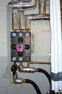
Figure 3: The rendeMIX connected between the CHP unit and the buffer storage causes the buffer to be loaded according to the two-zone principle and at the same time provides the return flow boost to the CHP unit.
By using three buffer connections, the storage tank is divided into two zones. Via the multi-way mixing manifold between the CHP unit and the buffer storage tank, the upper zone of the buffer storage tank is charged first (Fig. 4). Only when the upper zone is fully charged is the lower part included in the charging process. This means that the useful temperature is available more quickly at the top and the lower zone remains cold for longer.
- This two-zone charging acts as a return boost for the heat generator that is used to cover the base load. Here, the return to the heat generator is fed either with the mixture of hot heat generator flow and hot water from the middle buffer zone (phase I) or with a mixture of hot water from the middle buffer zone and cold heating water from the lower area of the buffer tank (phase II).
- In two-zone discharge, the heat distribution mixing circuit is supplied either with a mixture of the hot water from the middle buffer zone and the cold water from the mixing circuit return (phase I) or with a mixture of the hot water from the upper buffer connection and the hot water from the middle buffer connection (phase II).
Principle of return flow utilisation
- If there is excess heating heat in the return flow of the hot water stratified charging system (85/60 °C), the available temperature level is used to supply the mixed air heater heating circuit. In the same way, the return flow of the air heater heating circuit (80/60 °C) is also used for the radiator heating circuit (70/50 °C). Depending on the load, the heating energy of the mixed air heater return is used directly for the mixed radiator heating circuit via the multi-way mixing manifold or mixed with it. Only when the heat energy from the return is no longer sufficient to cover the heat demand do the mixing distributors access the buffer storage tanks.
-

Figure 4: The rendeMIX multiway mixing manifolds are controlled via the standard controls of the heat generators.
The lowest return temperature of the heat distribution is provided by the radiator heating circuit (50° C in the design state). This is fed into a separate, third return chamber of the heating distributor and thus flows back separately and without mixing into the lower zone of the buffer storage tank.
- The multi-way mixing manifolds have internal diverters. The different water quantities of the heating circuits connected in series are automatically balanced via the points.
- The specially developed three-chamber distributor is part of the HG Baunach range and is manufactured by Magra.
- All mixer drives are controlled by standard controllers with 230 V three-point signal depending on the temperature (Fig. 5).
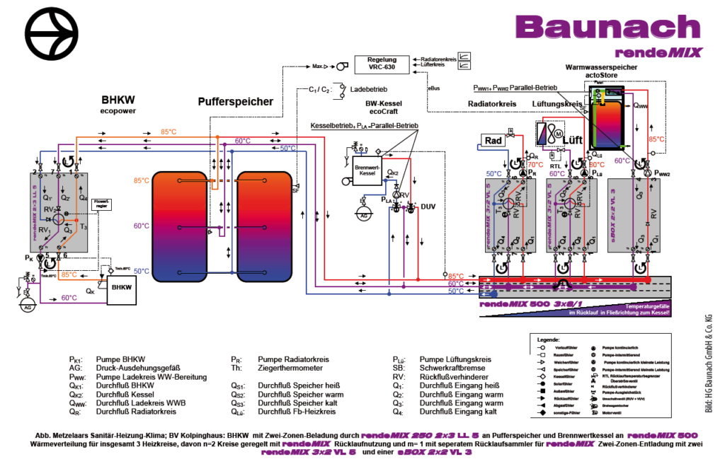
Figure 5: The rendeMIX multi-way mixing manifolds distribute the heating heat and supply the mixed heating circuits with their respective system temperatures. High return temperatures are used for the heating circuits with the respective lower system temperature. Together with the three-chamber manifold, low return temperatures are provided for the CHP and condensing boilers.
Summary
A large buffer volume with a high useful temperature is constantly available for the heating circuits due to the two-zone charging and discharging. The return utilisation ensures low return temperatures and thus long running times of the CHP module. It should also be mentioned that the control of the CHP unit and the condensing boiler are not interlocked. This control "freedom" results as a consequence of the stratification, which is set in stages in the buffer: this allows the priority of the heat generators to be determined simply but precisely via the position of the associated sensors.
The control of the gas condensing boiler monitors the set minimum temperature for DHW heating in the upper zone of the buffer. However, as long as the CHP unit provides sufficient heat, this minimum temperature is never undershot. Compared to the CHP running times, the boiler operation is consequently marginal: The operating data show, for example, that in the month of June, over a period of 210 h, the condensing boiler only had to fulfil its function as a peak-load boiler for DHW heating for 3 h. In the winter, too, despite the CHP providing sufficient heat, there is still a minimum temperature. Even in winter, the running times of the CHP remain constant despite the boiler operating at ten times its capacity. The control technology effort, however, could be kept to a minimum despite optimised system hydraulics, buffer management and return flow utilisation. The actuators for the rendeMIX mixing manifolds are controlled via the controllers, which are standard components of the heat generators used.
FUNCTIONAL PRINCIPLE rendeMIX
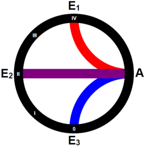 The actuator of the multi-way mixing manifold rendeMIX connects only two of its three inputs to the single output (A) at a time, so that either hot (E1) with warm (E2) or warm with cold (E3) water is mixed. In this way, as much available hot water as possible is used and only a little hot or cold water is mixed in. In this way, the temperature available in the heating water network is utilised to the maximum, and at the same time the return temperature to the heat generator is reduced. The actuator can be controlled by any weather-compensated controller (230 V three-point signal) from the boiler accessories. Alternatively, an actuator with integrated fixed value controller is available.
Wolfgang Heinl writes as a trade journalist for the SHK industry,
88239 Wangen im Allgäu,
wolfgang.heinl@t-online.de