
Pump speed and flow temperature
More efficiency at the buffer tank with less effort
 Some regenerative heat generators, such as wood or pellet boilers or CHP units, may only be operated with a fixed return temperature. For this purpose, a return flow increase (RLA) is used, which feeds parts of the heat generator flow into its return flow. Very often, the pump speed is selected unnecessarily high, which reduces the efficiency of the buffer storage loading.
Flow temperature decisive
The amount of heat that can ultimately be absorbed by the buffer storage tank depends not least on the flow temperature: if, for example, a 1 m³ buffer storage tank is heated from 30°C to 75°C, it can absorb up to 52.5 kWh; at 90°C flow temperature it would be 70 kWh - a whopping plus of 33%! A boiler with 35 kW would therefore have a maximum running time of 2 h at 90°C flow temperature, but only 1.5 h at 75°C.
Heat quantity = 7/6 × buffer volume × delta-T
Heat quantity = 7/6 × 1 m³ × (75-30)K = 52.5 kWh
Heat quantity = 7/6 × 1 m³ × (90-30)K = 70.0 kWh
Volume flow decisive
How can the flow temperature of a heat generator with RLA be raised? Quite simply by reducing the volume flow! If a heat generator with 35 kW output has a flow rate of 1 m³/h, its flow temperature is 30 K higher than the return temperature; with 2 m³/h it is only 15 K higher. If the fixed return temperature is 60°C, a flow rate of 2 m³/h results in a flow temperature of 75°C, and 1 m³/h results in a flow temperature of 90°C. Furthermore, halving the volume flow saves 7/8 or 87.5% of the electrically expended pump power.
Delta-T = 6/7 × power : flow rate
Delta-T = 6/7 × 35 kW : 1 m³/h = 30 K
Delta-T = 6/7 × 35 kW : 2 m³/h = 15 K
In the end, it's the layering that counts
But that's not all: in order for the buffer to be able to absorb the entire amount of heat, the 30°C cold water it contains must not be mixed with hot water from the heat generator. This is because loading can only be carried out until the buffer has reached 60°C at the bottom. After that, the return temperature can no longer be regulated to 60°C; the heat generator must be switched off. Responsible for the mixing of hot and cold water in the buffer tank is the volume flow through the buffer tank: the greater it is, the greater the turbulence and mixing of hot and cold water. It is therefore worth taking a look at the volume flows.
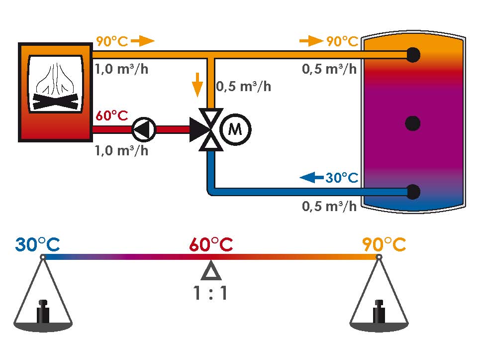
Figure 1a
Figure 1a shows a buffer tank less than half full, which is loaded by a boiler with 35 kW of heat. Water comes out of the lower buffer connection at a temperature of 30°C. The return lift (RLA), which keeps the boiler return temperature at 60°C, is flowed through by the pump with a volume flow of 1 m³/h. The delta-T is therefore 30. The delta-T is therefore 30 K and the flow temperature 90°C. The RLA therefore mixes water at 30°C and 90°C in equal parts of 0.5 m³/h each into the return. Consequently, the water flow rate through the buffer tank is also 0.5 m³/h.

Figure 1b
In Fig. 1b, on the other hand, the pump of the RLA was set to twice the volume flow of 2 m³/h. The delta-T at the heat generator is thus 15 K and the flow temperature 75°C. Thus, the delta-T at the heat generator is 15 K and the flow temperature is 75°C. Now two parts 75°C (1.33 m³/h) have to be mixed with one part 30°C (0.67 m³/h) to get the desired 60°C in the return. So the water flow through the buffer tank is now 0.67 m³/h, also a plus of 33%. Only this plus is a big minus for stratification! Because 33% more water throughput also means 33% more flow velocity, which results in 78% more kinetic energy, because: If you go 33% faster, you have a 78% longer braking distance.
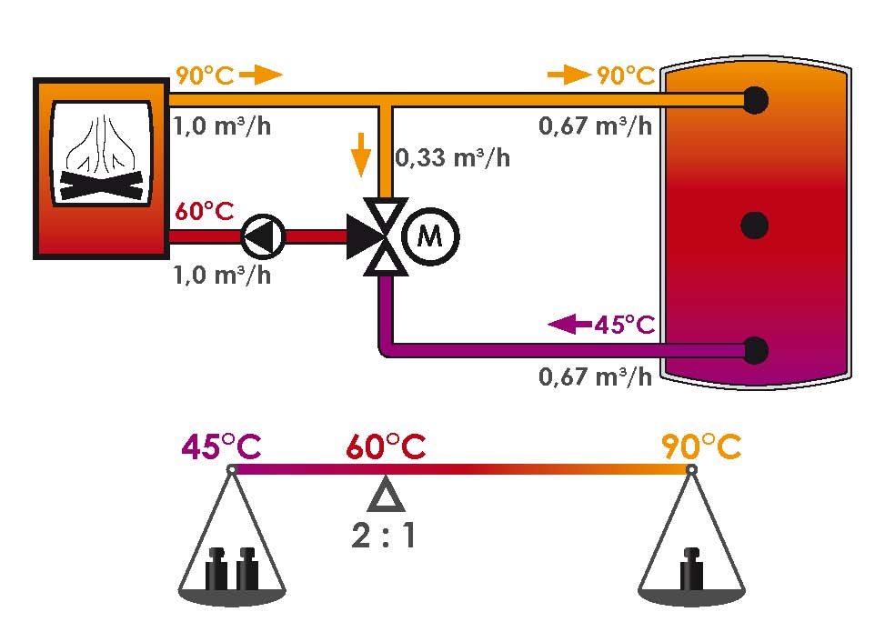
Figure 2a
Figure 2a shows the buffer tank more than half full. The return flow increase (RLA) keeps the boiler return temperature at 60°C; it is flowed through by the pump with a volume flow of 1 m³/h. The delta-T is therefore still 30 K and the flow temperature 90°C. The pump is not used for this purpose. The delta-T is therefore still 30 K and the flow temperature 90°C. The 35 kW boiler now takes the water from the lower buffer connection at a temperature of 45°C. The RLA therefore now mixes two water flows. The RLA therefore now mixes two parts of water at 45°C (0.67 m³/h) with one part at 90°C (0.33 m³/h) in the return. Consequently, the water flow rate of the buffer tank is now 0.67 m³/h.
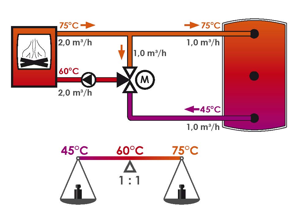
Figure 2b
In Fig. 2b, the pump of the RLA was again set to double the volume flow of 2 m³/h. The delta-T is thus 15 K and the flow temperature is 75°C. Thus the delta-T is 15 K and the flow temperature 75°C. Now 75°C must be mixed with 45°C in equal parts (1.0 m³/h each) to obtain the desired 60°C in the return. The water flow through the buffer tank is therefore now 1.0 m³/h, which corresponds to a plus of 50%. However, if you drive 50% faster, you have a braking distance that is 125% longer.
Everything at a glance
The summary is absolutely clear:
| low speed | high speed | |
|---|---|---|
| Heat quantity | large (+) | small (-) |
| Heat benefit | high (+) | low (-) |
| Power consumption | little (+) | much (-) |
Everything speaks for the smallest possible volume flow through the heat generator. This raises the question: How small can the volume flow actually be? Not so small that the maximum permissible flow temperature of the heat generator is exceeded! So it should be as small as possible, but as large as necessary. The best way to try this out is to bring the heat generator up to maximum output and then adjust the pump speed so that the highest possible flow temperature is reached, which ensures trouble-free operation.