


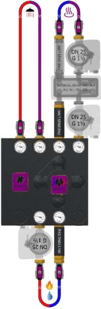
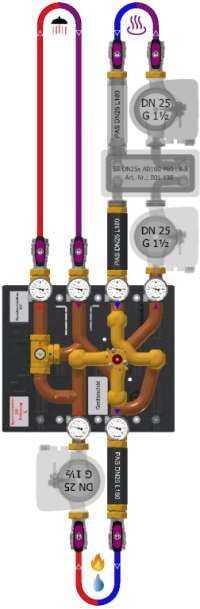
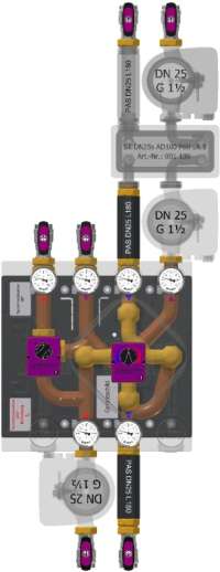
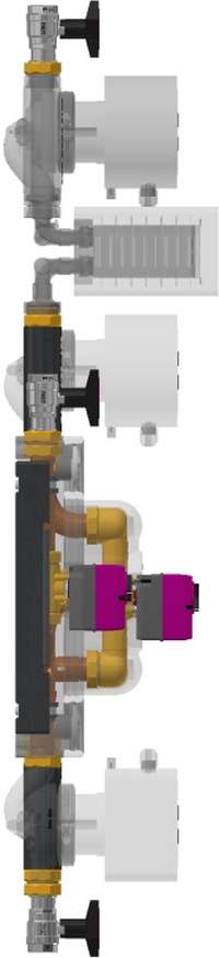
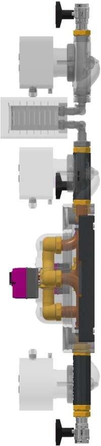
rSYS DN25s 2x4+UV R 15
Return utilization
For highly efficient use of the return flow of an unmixed high-temperature circuit (charging circuit) controlled by a changeover valve in a mixed low-temperature circuit (mixing circuit) by means of highly efficient operation of a system separation via flow control on a condensing boiler with minimum circulation
Required accessories


Recommended accessories

Configure product variant
Performance class
Pump flanges
Flow direction Producer
Product documentation
Assembly instructions
Specialist partner access required
Assembly instructions for motors
Specialist partner access required
Specialist partner access required
Spare parts drawing
Specialist partner access required
Data sheet
GAEB
Tender text
BAFA Funding Opportunity for Heating System Optimization Through Hydraulic Balancing and Installation of Separate Control TechnologyrendeMIX Multi-Port Mixing Manifold with 3/2-Way Tangential Mixing Valve DN25×G1½(a) MsGuss (red adapter) and 3-way mixing valve DN32×G1½(a) Ms58, valve body and cover Ms58For highly efficient utilization of the return flow from an unmixed high-temperature circuit (charging circuit) controlled by a diverter valve in a mixed low-temperature circuit (mixing circuit) through highly efficient operation of a system separation via flow control on a condensing boiler with minimum circulationCharging circuit: Actuator EMS 90-2P, 230V~ 50Hz 2.3VA 2-point signal, 6Nm (240h), 90°, 60s, left-closing, gray adapter. Mixing circuit: EMS 240 actuator, 230 V AC, 50 Hz, 3.5 VA, 3-point signal, 5 Nm (240 h), 240°, 93sDual-circuit manifold assembly with 2 connections to the heat source and 4 connections to the heat sinks, Cu Ø35×1, DN32×G1½(a) flat, pipe spacing 100 mm2 integrated gravity brakes/backflow preventers, Dp 10 mbarHeating circuit (HT): Kvs = 13.3 × V'max[100 mbar] = 4.2 m³/h × Q'max[20 K] = 98 kW × Leakage rate < 0.1% - Mixing circuit (NT) with ST DN25s: Kvs = 7.2 × V'max[100 mbar] = 2.3 m³/h × Q'max[10 K] = 27 kW × Leak rate < 0.1%6 thermometers 0–120°C, Ø63 mm, solder sleeves Ms586 ball valve fittings, straight-through DN25s, PN20, G1½(i)×Rp1 flat-seal, stuffing box, stem with nylon T-handleEPP insulation mold, 40 g/l, black, 450×450 mm, Quick-installation kitWith G1½(i) pump flanges for DN25 pumps on the heat generator supply line (1) and mixing circuit supply line (5)
Assembly includes TWO pump compensators—PAS L180—with G1½(a)×G1½(i) fittings to compensate for a DN25 pump, length 180 mm, insulated (Part No.: 001 338)Assembly does not include a pumpModel DN 25 – heavy-duty version, PN 10 bar, Tmax 120°CCAUTION: CANNOT BE USED WITHOUT SYSTEM ISOLATION!
Performance data
Charging circuit (HT): Kvs = 13.3 • V'max[100mbar] = 4.2m³/h • Q'max[20K] = 98kW • leakage rate < 0.1% - Mixing circuit (NT) with ST DN25s: Kvs = 7.2 • V'max[100mbar] = 2.3m³/h • Q'max[10K] = 27kW • leakage rate < 0.1%

-
Administration
- Übersicht
- Fachpartnersuche
-
Benachrichtigungen
-
Termine
-
Content-Bereich
-
Support
-
Analytics