


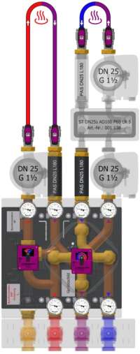
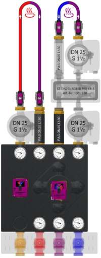
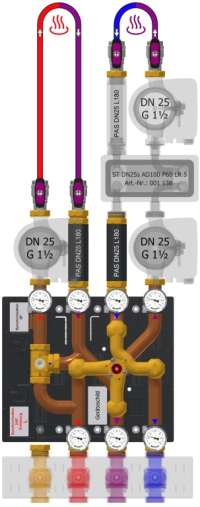
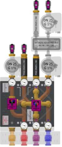
rSYS DN25s 3x4+3mix COPH
rSTOR C
For highly efficient two-zone discharge of an rSTOR C buffer storage tank in a mixed low-temperature circuit (2nd mixed circuit) through highly efficient operation of a system split via flow control, utilizing the return flow from a mixed high-temperature circuit highly efficiently, connected ABOVE a ball valve connection set (1st mixed circuit),
Configure product variant
Product documentation
Assembly instructions for motors
Specialist partner access required
Specialist partner access required
Spare parts drawing
Specialist partner access required
Data sheet
GAEB
Tender text
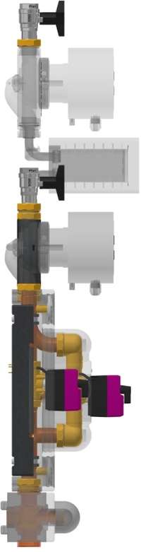
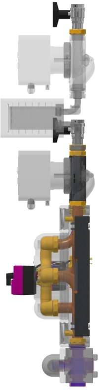
BAFA Funding Opportunity for Heating System Optimization Through Hydraulic Balancing and Installation of Separate Control Technology<br/>rendeMIX Multi-Port Mixing Manifold with 3/2-Way Tangential Mixing Valve DN25×G1½(a) MsGuss (red adapter), valve and cover Ms58<br/>For highly efficient two-zone discharge of an rSTOR C buffer tank in a mixed low-temperature circuit (2nd mixing circuit) via highly efficient operation of a system separation using flow control, with highly efficient utilization of the return flow from a mixed high-temperature circuit; connection ABOVE a ball valve connection set (1st mixing circuit),
1. Mixing circuit: Actuator EMS 90-3P, 230V~ 50Hz 3.5VA 3-point signal, 5Nm (240h), 90°, 70s, gray adapter. 2nd mixing circuit: EMS 240 actuator, 230 V~ 50 Hz 3.5 VA 3-point signal, 5 Nm (240 h), 240°, 93s<br/>Dual-circuit manifold assembly with 3 connections to the heat generator (buffer tank or boiler with flue gas heat exchanger), Cu Ø35×1, pipe spacing 100 mm, DN32×G1½(a) flat<br/>3 integrated gravity brakes/backflow preventers, Dp 10 mbar<br/>1st mixing circuit (HT): Kvs = 13.3 × V'max[100 mbar] = 4.2 m³/h • Q'max[20 K] = 98 kW • Leak rate < 0.1% - 2nd mixing circuit (NT) with ST DN25s: Kvs = 7.2 • V'max[100 mbar] = 2.3 m³/h • Q'max[10 K] = 27 kW • Leak rate < 0.1%<br/>7 thermometers 0–120°C, Ø63 mm, solder sleeves Ms58<br/>4 ball valve fittings, straight-through DN25s, PN20, G1½(i)×Rp1 flat-seal, stuffing box, stem with nylon T-handle<br/>EPP insulation mold, 40 g/l, black, 450×450 mm, Quick-installation kit<br/>With G1½(i) pump flanges for DN25 pumps on the 1st mixed high-temperature (3) and 2nd mixed low-temperature circuit supply lines (5)
Assembly includes TWO pump compensators—PAS L180—with G1½(a)×G1½(i) fittings for compensating a DN25 pump, length 180 mm, insulated (Part No.: 001 338)<br/>With a blind fitting consisting of a G1½ brass union nut and a stainless steel washer<br/>Model DN 25—heavy-duty version, PN 10 bar, Tmax 120°C<br/>CAUTION: NOT TO BE USED WITHOUT SYSTEM ISOLATION!
Performance data
1st mixing circuit (HT): Kvs = 13.3 • V'max[100mbar] = 4.2m³/h • Q'max[20K] = 98kW • leakage rate < 0.1% - 2nd mixing circuit (NT) with ST DN25s: Kvs = 7.2 • V'max[100mbar] = 2.3m³/h • Q'max[10K] = 27kW • leakage rate < 0.1%
-
Administration
- Übersicht
- Fachpartnersuche
-
Benachrichtigungen
-
Termine
-
Content-Bereich
-
Support
-
Analytics