
Sports facilities must not be a poor relation
 Case study CHP-supported heating system German Table Tennis Centre
The individual and new heating technology components in the refurbished German Table Tennis Centre Düsseldorf Therefore, the emphasis on "innovative" is not appropriate because the components are several years past the stage of innovation: Condensing boiler and CHP systems are now state of the art and the multi-way mixer principle is becoming more and more widespread. What makes the installation in the DTTZ nevertheless worth reporting on is the location of the exemplary heat supply, namely in the sports facility, which is normally the poor relation in terms of heating technology, the intelligence of the device combination in terms of circuitry and its documented effectiveness.
The public clients deliberately invested in an exemplary TGA, setting an example for similar facilities. Of course, the renovation package can only be an exemplary model if it proves itself. The first results, however, already speak clearly in favour of it, as is evident from the informative measurement protocols. This is what we are talking about: one of the cornerstones of the German table tennis team's runner-up finish in Tokyo in 2014 lies in Düsseldorf. More precisely in the district of Grafenberg and there in the German Table Tennis Centre DTTZ (Fig. 1), which is located in the buildings of the traditional club Borussia Düsseldorf. Borussia's display cases contain a myriad of trophies for German championships won. Active members of the club regularly belong to the absolute world elite, such as Steffen Fetzner and Jörg Rosskopf, who won the doubles at the 1989 World Championships, or current professional Timo Boll. He managed the feat of playing himself temporarily into first place in the world rankings ahead of the overpowering Chinese.
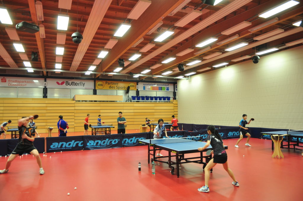
Picture 1: German Table Tennis Centre Düsseldorf (DTTZ)
Unique in Germany
In 2006, the German Table Tennis Association DTTB had moved its talent factory from Heidelberg to Düsseldorf. The facility and the possibilities around the record champion Borussia offered more efficient structures for the promotion of future generations. This means that both the DTTB and the financiers of the project - the city of Düsseldorf (50 %), the state of North Rhine-Westphalia (30 %) and the federal government (20 %) - naturally have expectations of the investment of 5 million euros in the national base (with boarding school).
Currently being number 2 behind China fulfils claims of this kind for the national team. But the durability of a top ranking depends in part on the continuous use and usability of the facility, ergo on its attractiveness. The parties involved were therefore aware that they would be faced with follow-up costs. In 2006, when the training and competition facility was handed over to the DTTB, the planners estimated the annual operating expenses for technology alone at 200,000 euros. One reason for this relatively high item is hidden in the interlocking of old and new. The realised design with integration of the national base into the real estate of the Grafenberg club had to make use of existing installations as far as possible with regard to the energy supply - which, however, applies to renovations in general. More than 5 million euros for buildings and technology were not available.
New and old interlocked
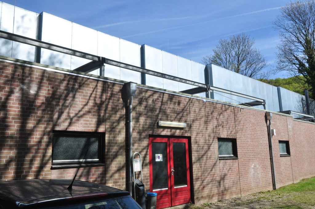
Figure 2: Part of the ventilation system
The building complex dates back to 1994, when it was built by a Dutch general contractor. He had brought his subcontractor heating technology - gas atmospheric - from the Netherlands. However, both the general contractor and the plant manufacturer withdrew after construction. For many years, the Düsseldorf company Florack GmbH has been in charge of the building services. This provided plenty of work. Defects appeared relatively quickly in the old system, starting with the control system and ending with defects in the single-pipe heating system, for example in the valves. The lines had plenty of these: 240 of them. Repairs and partial renovations filled the order book. At some point, a ventilation system for the large hall was added, so that the boiler no longer managed to keep the buildings at a comfortable temperature, even if it ran 24 hours a day. The additional 120 kW for ventilation exceeded its power reserve. For the time being, the heat generator had no choice but to distribute a deficiency.
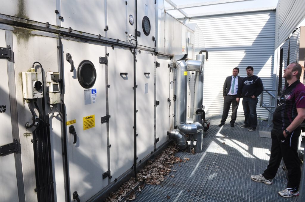
Photo 3: The ventilation system only received a dehumidification stage in later years. Before the measure, the professionals played on unfavourable days literally enveloped in a veil of moisture. In the picture on the right, DTTZ employee and building technician Danilo Enz; in the background, next to Peter Weber, CHP consultant Thilo Braun from the Vaillant company.
This deficiency became more and more apparent with the increasing popularity of table tennis due to the success of the national team as well as the club Borussia Düsseldorf: damp and wet indoor haze instead of forehand-oriented indoor air conditions. Forehand-oriented means that the sport with celluloid is generally known for its susceptibility to wind and tension. The feather-light ball weighs only 2.7 grams, so almost any breeze from the side blows it out of the desired direction. Less well known, however, is the considerable influence of humidity on the trajectory. The pros play with topspin. This special hitting technique sets the ball in rotation, which makes its direction difficult to calculate after it bounces off the plate.
Hardly any topspin in damp conditions
The higher the friction between ball and club, the higher the spin. Moisture, on the other hand, weakens the result. It literally coats the pimple coating of the playing equipment with a film of grease. The ball gets no spin, it becomes calculable for the opponent. The old system was set up like this: In principle, the radiant ceiling panels (see Fig. 1) ran in combination with a high proportion of fresh air. The supply air flowed undehumidified under the ceiling to the registers, which heated them up and pushed them down. This increased the relative humidity in the hall, especially on humid and rainy days. During Bundesliga or national team matches with a thousand or more spectators, the relative humidity was already close to the permissible limit. "Permissible" here does not refer to hygienic comfort conditions, "permissible" refers to celluloid ball and racket. "On unfortunate days, we really played in the fog," Jo Pörsch, Managing Director of Borussia Düsseldorf e. V., looks back. In 2009, therefore, the ventilation system (Fig. 2) was converted into an air-conditioning system, the fresh air was prevented from passing over the ceiling radiators - the panels through which heating water flows were, however, retained - and instead directed through a proper dehumidification stage (Fig. 3) as one of the first retrofitting measures. This retrofit ensured a reasonable playing operation again.
Economical CHP

Figure 4: Heat (and electricity) generation in the renovated DTTZ is provided by a Vaillant CHP unit with 4.7 kW of electricity and 12.5 kW of heat, as well as an "Ecocraft" gas condensing boiler. On the right, plant engineer Peter Weber from the plant construction company Florack GmbH, Düsseldorf, in the middle, energy consultant Martin Halbrügge from Ecoteam, Halver. Far left, rendeMIX developer Hans-Georg Baunach.
With this and other expansions, the time of the atmospheric gas boiler was definitely over. As mentioned, it could only supply the property with a maximum flow temperature of 40 °C during the heating season. In 2013, therefore, the building services were completely renovated: among other things, with a gas condensing boiler, which, on the advice of the environmental agency of the city of Düsseldorf, is supported by a small CHP unit. Why the environmental agency? Because, against the background of the climate debate, the authority of the state capital offers sports clubs advice on energy-efficient installations. Energy efficiency is not necessarily a top priority in many club-owned properties. Although every club management observes the development of energy and operating costs with suspicion, they are seldom among the main topics of work in view of the heterogeneous interests of the members. The members primarily want a functioning, not an economical heat supply. The public sector, on the other hand, as a financing or subsidising authority, sees electricity and heating primarily as a cost factor. Speaking of the cost factor: Why did the authorities support a small CHP plant despite the city's notoriously tight finances? "There is a public interest in sports facilities. When it comes to investments, the public sector therefore contributes a certain percentage. This applies to all district sports facilities. If ecological requirements are now taken into account, the city is also prepared to take responsibility for a somewhat higher subsidy. That is what happened in this case," explains the semi-official energy consultant Martin Halbrügge. His engineering office IAS Halbrügge entrusted the environmental office with the energy support of the DTTZ, with the creation of a master plan - hence the attribute "semi-official".
Crucial: Analysis of load profiles
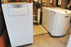
Fig. 5: The cramped technical room called for a compact installation
Strictly speaking, it is not just about a public interest, it is about a public building. The new building added in 2005/2006 with the construction of the German Table Tennis Centre on the Borussia site is municipal. And the small ball players built their own brick building in 1994, also largely with funds from the federal government, the state and the city, because even then the training facility had significance beyond the club level. "Our basic work," the specialist engineer describes, "consisted first of all of a consumption analysis. The CHP unit was a natural choice when the thermal and electrical requirements became apparent. Thermal: In the 16 hotel rooms alone, shower water flows two to three times a day, namely after every training session, and that for more than 300 days a year. When no training course is scheduled, exhibitors and visitors of the numerous Düsseldorf trade fairs like to stay in the boarding school hotel. Electrical needs for lighting, for pumps, for equipment, exist all year round anyway." Martin Halbrügge recorded the load profiles and calculated enormous cost savings if a CHP unit was installed, as the complex would or could consume its own generated electricity for 8,000 hours or more a year. The selected "Ecopower" unit from Vaillant (Fig. 4) with an output of 12.5 kW thermal (4.7 kW electrical) looks modest compared to the total demand of 280 kW thermal, but the 280 kW takes into account the most unfavourable winter case with filled training rooms, hotel occupancy, competition (spectator stands) and other additives. The heat demand is subject to considerable fluctuations in a sports centre with a hotel.
No losses due to new EEG
Incidentally, because of the 4.7 kW electric, the new regulations on the payment of the EEG levy do not gnaw at the economic viability of the "Ecopower". Although the new CHP (which goes into operation after 1 August 2014) must now also make a financial contribution to the expansion of "renewables", the cancellation of the previous exemption from the EEG obolus only affects machines over 10 kW electric. "And with the maintenance contract, the operator is on the safe side. Although he does not have to worry much about the reliability of the unit anyway. We have been working with Remscheid for years, both in terms of cogeneration and gas heat generation, and there has not been a single problem worth mentioning," says Peter Weber, Managing Director of Florack GmbH, explaining why he advised his client to combine the "Ecopower" with the "Ecocraft" condensing boiler. Peter Weber had received design support with regard to Vaillant energy technology from Thilo Braun, graduate engineer and sales engineer for renewable energies at one of the world's leading companies for heating and energy technology (Vaillant turnover 2013 total group 2.381 billion euros, 12,000 employees). Florack GmbH's expertise in CHP was available to the customer DTTZ in the form of a quasi-licence, issued by Vaillant. The manufacturer is concerned about the risk of its leading name being damaged by poor workmanship. The damage could cast a shadow over the entire brand. Therefore, only Vaillant customers who have been intensively trained at the factory receive the CHP technology, the maintenance and spare parts and the warranty promise.
Multi-way mixing principle as a way out
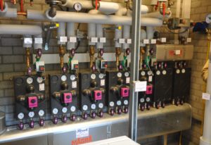
Figure 6: Mixer installation for five heating circuits plus one uncontrolled high-temperature circuit (ventilation, right). The heating circuits controlled by "rendeMIX" serve, among others, the radiant ceiling panels (large hall) and the radiator systems (hotel, small hall, changing room). For details, see also the section "Evaluation of the temperature recordings".
A sufficiently dimensioned buffer storage tank belongs to the CHP unit and boiler in order to optimise efficiency. The renovation also included renewing the partially dilapidated heat distribution system. As mentioned earlier, some mixers and valves no longer functioned and the pumps fell into the category of "energy guzzlers". However, the technical centre was already bursting at the seams (Fig. 5). The site did not allow for an additional extension. The parties involved therefore had to resort to a compact system with a moderate storage volume of 1,500 l for the entire sports and hotel grounds and realise some special technical features in order not to have to accept major cutbacks in economic efficiency. The integration of the "rendeMIX" multi-way mixer, for example, was a logical step. Only this sensible development (Fig. 6) makes it possible in principle to get by with a relatively small storage tank: in that the control valve carries out a much more stable stratification and an energy-saving charging and discharging. The result is a buffer that, because of its two-zone charging and discharging, offers almost twice the capacity of a conventional single-zone charging and discharging with the same content.
Hot stays hot longer
In addition, the mixer does not send hot return water back to the storage tank when required, but directly into such heating circuits to which this flow temperature from the radiant ceiling panels, for example, lies somewhere between 45 and 50° C. This level is quite sufficient for certain low-temperature circuits as a flow. "We combine two techniques here, dual-zone discharge, where if it is sufficient for some consumers, we first take the hot water from the middle and cool it down before accessing the valuable hot water from the upper buffer zone, with return utilisation. This means that the strings of the high-temperature circuit make their return available to the middle connections as a flow" (Fig. 8), Hans-Georg Baunach, developer of the "rendeMIX", explains the savings scheme. Legionella prophylaxis and hygienic drinking water supply were naturally also at the top of the agenda during the renovation and modernisation. The planners did not find it easy to answer the question of how to cover peak demand. A training centre plus hotel does not fit into the usual dimensioning rules for storage tanks. Therefore, system builder Florack and the Halbrügge office first implemented hot water meters to analyse consumption. On Vaillant's recommendation, they installed the "Zeeh" system from Joachim Zeeh in Bockau/Erzgebirge, Saxony, after evaluating the measurement results because of its high flexibility. The Remscheid-based CHP supplier has been working with the Saxon for some time.
Water heater with turbocharger
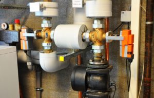
Fig. 7: The boiler circuit runs via two changeover valves (with orange actuators). In weather-compensated heating mode (with priority hot water mode), the multi-way mixer draws hot water from the buffer 40 from below (Fig. 8), feeds it to the boiler and returns it to the centre connection via the corresponding valve position. In priority mode, both valves switch over, i.e. the mixer draws from the middle and feeds back at the top.
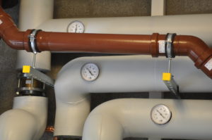
Figure 8: Buffer connections with currently 65 °C at the top, with 44 °C at the middle and 40 °C at the bottom connection.
In principle, this is a heating buffer storage tank with integrated hot water preparation in flow mode (Fig. 9). At the top, in the hot zone of the storage tank, a corrugated steel pipe (i.e. with a large surface area) hangs coaxially in a jacket pipe. This unit thus forms a counterflow heat exchanger: cold water flows upwards in the corrugated stainless steel pipe and heating water flows downwards from the hottest point of the storage tank to settle cooled (approx. 15 °C) at the lowest point. This happens mainly without electrical energy. Only during peak tappings or at low storage temperatures does a charging pump switch on automatically - depending on the temperature difference and the flow rate - modulating and increasing the flow rate ("turbocharger") to quickly bring the coil with its approx. 40 l capacity up to temperature. Due to the lack of sufficient residence time and the high temperatures, legionella do not thrive in this environment.
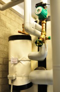
Figure 9: Charging system of the "Zeeh" storage tank. When the domestic hot water temperature drops, the charging pump starts up and directs additional storage water through the pipe heat exchanger, similar to a turbocharger system.
Of course, circulation disinfection of the connecting pipes must still be ensured. An additional small high-temperature heat exchanger in the tank in the form of an integrated circulation lance in the corrugated pipe saves heating energy. In this way, the aim is to keep germs in the entire system to a minimum. The health authorities are regularly convinced of this, and not only according to the new Drinking Water Ordinance. Public buildings, sports facilities, swimming pools, schools and kindergartens have always been inspected regularly. As far as the technology is concerned, it should be mentioned that the return flow of the circulation system enters the hot zone of the buffer at just under 60 °C, thus stabilising the stratification.
Why the CHP fits into the scheme
 Vaillant's "Ecopower" block produces 70 °C. They control the temperature of the hot water with complete confidence. The ventilation system also wants high temperatures, as relatively small exchangers have to raise 30,000 m³ of supply air to room temperature every hour at temperatures as low as minus 10 °C, so to speak. The crucial thing here is dehumidification to prevent fogging in the hall. The unit first cools the air for dehumidification, but then has to raise the cold air to the supply air level in a short time with a relatively high temperature in a constricted exchanger area. These temperature peaks are "automatically" supplied by the CHP unit. In any case, boiler manufacturers usually demand a limitation of the maximum spread, and the CHP unit meets this demand.
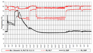
 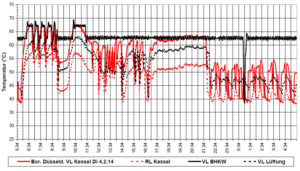 For as long as the system can operate in weather-compensated mode to cover the heating load in a temperature range below 50 °C, the CHP unit will make an effort to load the buffer at the top with the necessary peak temperature to allow the boiler to provide the low temperature level in an energy-saving manner. The temperature messages from the changeover valves decide whether the condensing boiler or the CHP unit operates. VUV means flow changeover valve and RUV means return changeover valve. Some temperature and operating states are shown in the diagrams. Before the refurbishment (upper diagram), the boiler (red) supplied 24 hours of high temperature for radiant ceiling panels and ventilation, and there was no demand-oriented control of the flow temperature.
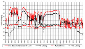
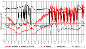 In the second diagram from above, after the refurbishment, the condensing boiler covers the base load via the storage tank. On a mild Sunday, 26.01.2014, the boiler only runs at night with regard to the ventilation flow (third diagram). During the day, its flow temperature fluctuated between 40 and 50 °C and the ventilation supplied itself from the potential of the storage tank. When the ventilation comes on at 50 or 60 kW, however, the storage quickly reaches its limits. The boiler has to do the work. The diagram below shows the temperature curves after installation of the demand-oriented control of the flow temperatures.
Evaluation of the temperature recordings
Starting point
The operating data of the heating system in the DTTZ Borussia Düsseldorf (Figure 10 shows the demand in the DTTZ complex) were logged before and after the refurbishment in order to be able to track the success of the refurbishment and modernisation. The following recordings took place: March 2013 ? Water consumption after installation of water meters in the hot water tank inlets ? Heating circuit temperatures ? Boiler temperature August 2013 ? Recording of the operating behaviour of the CHP January-February 2014 ? Operating temperatures of condensing boiler and CHP unit ? Return temperatures of all heating circuits and ventilation separately In addition, the meters have been read regularly since commissioning.
Assessment of the old plant
The records show that the heat generator was no longer controlled according to demand, but ran at the maximum operating temperature 24 hours a day via the boiler thermostat. The flow temperatures of the heating circuits were adjusted according to the times of use, but the spreads were rather small. The ventilation was undersupplied. By means of the installed water meters, it was possible to determine the hot water consumption and also obtain reference values regarding the impact load. The gas meter readings provided information on the required heating load.
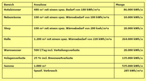
Figure 10: Demand in the DTTZ-Borussia complex
By observing the operating behaviour, the following points could be improved quickly directly after commissioning:
- Switching behaviour of the CHP unit
By observing the switch-on and switch-off behaviour of the CHP unit, it was possible to optimise the positioning of the corresponding sensors on the buffer. The CHP unit should always take over heat generation as a priority and at the same time run for as long as possible, so that a high proportion of own electricity coverage is achieved. The positioning of the sensors can influence the switching behaviour; the positioning depends on the interaction of the buffer capacity with the heat consumption of the heating circuits and the hot water preparation.
Detail mixer principle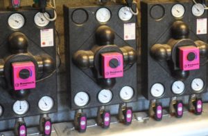
On the right, the two mixers are about one third in the blue scale, i.e. they currently only supply themselves from the middle buffer chamber and their own return flow. The mixer on the left is supplied with about two thirds from the middle chamber and one third flows from the upper chamber. Each of the Baunach mixers always takes hot water from the middle connection over large parts of the operating range. This has the energetic advantage that this water comes either directly from a return flow of the high-temperature circuits or from the middle chamber of the buffer. In both cases, it is mixed water, i.e. of lesser benefit in terms of heat storage. The water with the highest benefit for heat storage is either completely hot or completely cold. Prioritised withdrawal of mixed water increases the cold and hot water capacity.
- Temperature spread ventilation-heating circuits
The special hydraulic conditions in the ventilation heating circuit initially resulted in uncontrollably high return temperatures; this could be corrected by retrofitting return temperature limiters.
- Temperature curves after initial optimisation
The records almost half a year after commissioning of the modernised plant impressively show the technical improvements (see also pictures in Box 1):
- Operating behaviour heat generator
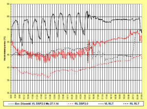
Fig. 11: The "rendeMIX" multi-way mixer makes it possible: The return RLT of 45 to 50° C extends as a flow to the radiant ceiling panels and thus has a low temperature level that ensures condensation in the condensing boiler. Without a Baunach mixer, condensation gains and further flue gas heat would be wasted.
The CHP runs almost 24 hours a day. The condensing boiler only switches on when required, if the necessary flow temperatures are no longer reached at the distributor. The buffer gives the Ecocraft enough time to start up, and it also reduces its output again when the flow temperatures are reached. While the CHP basically generates heat at a high temperature level, the condensing boiler only runs at the maximum flow temperature required at any given time, which favours the utilisation of the condensing value.
- Takeover of heating load by the CHP unit
The temperature curves show how the buffer helps to shift the heating load to the CHP unit. It is possible to temporarily satisfy the high temperature requirements of the heating circuits from the buffer and thus use the condensing boiler as little as possible.
- Heat utilisation of the heating circuits
The temperature levels, especially the return temperatures, show the potential of the Baunach mixer (Fig. 11). The comparatively high return temperatures of the ventilation can be used in the other heating circuits, especially in the radiant ceiling panels of the gymnasiums. In this way, auxiliary energy is reduced and the heat generation is relieved. Above all, the greater cooling of the return favours the utilisation of calorific value, and stratification in the buffer.
- Hot water preparation without problem
Since the hot water is prepared in the buffer and this is permanently supplied directly by the CHP unit, the hot water load cannot be recognised from the temperatures in the buffer. So far, however, the taps have not been undersupplied, even at peak times.
- Gas consumption including electricity generation
The evaluation of the gas consumption at the main meter shows that the heating load, based on 24 h per day, did not exceed 90 kW. With reference to 15 h per day, the value increases to 140 kW. These values are lower than those of the old system, although they still include electricity consumption. Here one can see the efficiency gain of the modernisation. Keeping a reserve is justifiable because it cannot be assumed that all system components always work together optimally and in extreme cases higher loads can occur (for example, heating up the hall from a cold state).
- Operation of the heating circuits
The temperature recordings show that comparatively good spreads are achieved, although there are limits here due to the single-pipe heating system. The return temperature level in the sum of all heating circuits is close to the dew point of the flue gases; in a further test phase, the actual amount of condensate produced is to be recorded and evaluated. It is also already being considered to install return temperature limiters, similar to those in the two air heating coils, in order to reduce the boiler output if the return temperature exceeds a limit value.
Basic structure of a rehabilitation
 Requirements for the construction and operation of an efficient and reliable heating system
The most frequent reason for a heating system renewal is the failure of the boiler or other indispensable components such as the control system. Technical development has, however, redefined the package of measures to be taken in the event of a heating system renovation. Today, many more factors must be taken into account and the system components must be carefully coordinated. The following are the central points using the example of the heating system refurbishment carried out in 2013/2014 at the Borussia Düsseldorf TTZ.
1.technical concept
We are required to handle energy carefully and to use regenerative and rational energy generation options. Before simply replacing a boiler, the question should therefore always be asked as to what options exist in this regard in the course of an upcoming boiler replacement.
Use of solar energy
- Generating own electricity by means of combined heat and power generation
- Installation of highly efficient heat generation technology
- Installation of high-efficiency pumps
- Choice of particularly efficient hydraulic solutions
- Choice of special control strategies
In almost all points, the renovation of the DTTZ heating centre has special features that contribute to making the system efficient and operationally reliable. In addition to the existing planning documents, the concept should be based on supplementary measurements or current operating experience with the existing system. Instead of factoring in safety margins, the real demand should be recorded as accurately as possible. This applies in particular to the required heating load, the hot water demand and the hot water load profile. The following points can be determined with simple means:
Heating load
Points of reference are the existing boiler output, the calculated heating load demand and the current boiler utilisation (meter readings to determine the current outdoor temperature-dependent heating load).
Circulating pump performance
The set pump capacities must be documented here.
Time programmes for the connected heating circuits
The time programmes set on the old control system should be documented and compared with the actual times of use. Long lead times often indicate supply problems.
Heating curves
The set heating curves should also be documented. If the heating circuits are not calibrated, excessive heating curves are often run.
Hot water quantities
By installing a water meter in the access to the storage tank, the hot water demand can be specifically tracked and determined. This facilitates the design of the storage tank and enables a careful, reliable estimate of the potential for the use of solar energy. Oversized storage tanks have a negative effect on the solar contribution margin.
Hot water tap profile
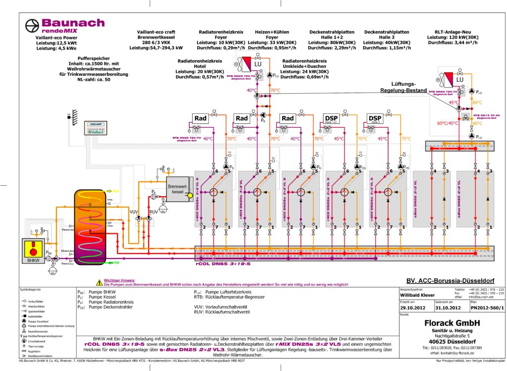
The meter also makes it possible to determine the tapping profile if you read the meter more frequently, especially at peak times. Knowledge of the tapping profile is of central importance for the design of the hot water heat exchanger. Taking all of the above parameters into account, the DTTZ created the hydraulics in the adjacent circuit diagram with some special technical features.
2.technical solutions
2.1 Combined heat and power generation
From an electricity demand of more than 20,000 kWh/a and a year-round heat demand, the use of combined heat and power is usually the best option. Proper design, hydraulic integration and control ensure economical operation. Care should be taken to ensure that the CHP unit achieves the longest possible running times and that the electricity generated is largely consumed by the unit itself.
2.2 Condensing boiler
While spreads of 10 to 20 K are common with conventional boilers, effective condensing boiler systems can also achieve 20 to 30 K, which then again comes up against limits with the boilers. The following should be aimed for: low distribution temperatures (if possible surface heating), low return temperature (high spread) and operation independent of room air (combustion air preheating).
2.3 Buffer tank as hydraulic separator
In buildings with several heating circuits, a hydraulic decoupling of heat generation and heat distribution makes sense; only in this way can the individual components be operated optimally. In many systems, hydraulic separators are used for decoupling. However, these have the disadvantage that they destroy temperature stratification and therefore impair the efficiency of energy-saving solutions such as condensing boiler technology, heat pump or solar technology.
2.4 Buffer storage as combined storage for heating and hot water preparation
Since combined heat and power and hot water production both benefit from heat storage, it makes sense to realise these requirements by using a combi-storage tank in one component. This also has the advantage of saving space. With reference to the above aspect, the storage tank should also function as a hydraulic separator with a temperature stratifying effect. The Zeeh storage tank used in the DTTZ fulfils these requirements in an exemplary manner.
2.5 Heating operating conditions (time programme and flow temperature level)
In order to be able to run low heating curves, it is necessary to hydraulically balance the individual heating circuits, i.e. to adjust the flow rates at full load to the determined heating load. Hydraulic balancing is a prerequisite for minimum operating temperatures and maximum spread.
2.6 Distributor 3-wire technology
There are usually different temperature levels in branched distribution networks. A typical example is the combination of underfloor heating, radiator heating and ventilation heating. The return temperatures of a radiator heating circuit can be used well as a flow for an underfloor heating circuit. In this way, it is possible to cool down and reduce the circulating water quantities to a greater extent and thus also make heat generation more efficient (higher efficiency of condensing heat generation, lower auxiliary energy demand of the circulation pumps).
2.7 Use of high-efficiency pumps
The use of high-efficiency pumps is compulsory today, but it is not yet consistently taken into account that a changeover to this technology only works smoothly and with the full effect if the heating circuits are hydraulically balanced. Not only should more efficient pumps be used, but the volume flows should also be reduced in order to achieve high spreads.
2.8 Return temperature limitation
Return water should be as cold as possible. This can be effectively regulated by using a return temperature limiter.
3. plant optimisation
After a system renovation or modernisation, a phase of adjustment and success control should always be planned.
3.1 Adjustment
Although a complex system can be calculated theoretically, it still needs a regulation phase so that the flow rates and heating curves are set to the minimum necessary values according to demand. It is good if the adjustment phase is accompanied by temperature curve recordings and these curves are also carefully documented for later evaluations. It can also be helpful to make the curves in the boiler room visible to the operating staff.
3.2 Consumption control
The consumption control can then be used to check once again whether the desired success has been achieved. The consumption control should at least include the determination of the annual values; it is better to have snapshots based on daily values so that a system control is possible at any time, even at short notice.
4. plant components
4.1 Baunach mixer
The Baunach mixer is a development for the more effective operation of heating circuits. Among other things, it makes warm return water from high-temperature circuits available to the low-temperature circuits as a flow. The advantage of this technology is that the volume flows to be circulated are reduced and the temperature spread is increased for more effective utilisation of the calorific value.
4.2 Charging and discharging technology Buffer tank
Here, too, special technology from HG Baunach GmbH & Co. KG, which enables more effective loading and unloading of the buffer storage tank. To react quickly to heat demands, the flow and return are switched over simultaneously, which also improves the interaction of the two heat generators.
4.3 Hot water heating with corrugated tube heat exchanger
The use of buffer storage tanks with corrugated tube heat exchangers is quite common in smaller output ranges, but is actually unusual for the requirements that exist here. However, since this principle of water heating is considered to be very solid and not very susceptible, the storage tank was specially designed by the manufacturer for the special requirements at Borussia Düsseldorf. The advantage of the solution is that technically complex fresh water stations can be dispensed with and yet the hot water preparation is extremely hygienic. Thanks to a special technical feature of the storage tank, it is also possible to realise higher hot water outputs when required. This is particularly interesting for sports clubs, which often have to deal with short-term peak loads.
4.4 Combination of CHP unit and condensing boiler
The hydraulic integration of a combined heat and power unit, in the DTTZ the "Ecopower" type from Vaillant, is one of the major challenges of a self-generated electricity system. By generating its own electricity, the association can make itself independent of the purchase of public electricity to the extent that it succeeds in achieving a high contribution margin. The prerequisite for a high contribution margin is that the CHP unit achieves the longest possible running times and that the heat generated is used skilfully. The economic benefit depends decisively on the hydraulic integration, the dimensioning of the buffer storage tank and the correct positioning of the temperature sensors that switch on and off. The first balances since commissioning in August are very promising; the CHP generates more electricity in total than the DTTZ needs, and only a few kilowatt hours of electricity have to be purchased to bridge peak loads.
Martin Halbrügge, Ecoteam
www.ecoteam-nrw.de
Dipl.-Ing. Bernd Genath is a freelance journalist, Düsseldorf.
Download the technical article as PDF
