The jet principle - Regenerative solution for system separations in mixed circuits
 Heat exchangers are often used, especially in renovation, to separate older diffusion-open underfloor heating from the rest of the system. This not only leads to the use of additional pumps, but usually also to a significant increase in return temperatures. Especially in solar and condensing systems, this considerably reduces the coverage rates and efficiency. A new technical approach promises to remedy this situation.
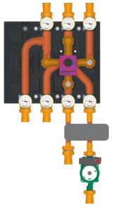
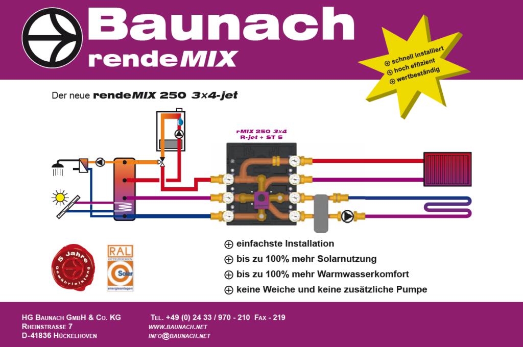
Feed without pump into the system separation rJET DN25 3×4.
Regulatory standard for district heating transfer stations
Heat exchangers (WT) are often used in transfer stations of district heating networks. The best and simplest solution for controlling the secondary-side flow temperature TVsek is the control of the heat supply via the primary side flow rate Qprim' which always leads to the lowest possible primary-side return temperature TRprim and thus also leads to the lowest possible flow rate on the primary side. In networks with differential inlet pressure, a motorised control valve (ReV), which is controlled by a commercially available three-point control (open/stop/close), is sufficient for this purpose. The maximum flow rate is usually limited by a differential pressure-controlled throttle valve (DrV), Fig. 1. Even when connecting non-diffusion-tight underfloor heating circuits to modern heat generators
(condensing boilers), system separations are often required by the manufacturers. If it is a two-circuit system, this low-temperature circuit must also be controlled as a second heating circuit via three-point control. Here, too, the control valve (ReV) is the simplest and best solution with regard to the control of the heating system.
to the lowest return temperature on the primary side TRprim and the smallest flow rate Qprim Fig. 2.
Return flow utilisation increases condensing boiler utilisation rates
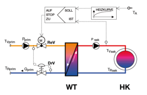
Fig. 1: Flow control of a heat transfer station with primary-side control valve.
With the rendeMIX 2×4 multi-way mixing manifolds for dual-circuit systems, the method of using the return flow was introduced to the market for the first time. In this process, a multi-way mixer with its three inputs for supplying the low-temperature circuit first uses the return flow of the high-temperature circuit via E 2 before accessing the hot boiler flow via E 1. This leads to a series connection of both heating circuits with the consequence of decreasing return temperatures and flow rates in the heat generator. This multi-way mixing valve can also be controlled by a servomotor via a three-point control. The two heating circuits are hydraulically decoupled by means of a compensating section in the assembly, which acts like an internal separator: If the high-temperature circuit supplies more water than the multiway mixing valve draws into the mixing circuit via its input E 2, the surplus flows to the boiler return (flow direction b); in the opposite case, the deficit is drawn back from the low-temperature circuit (flow direction a). There is no need to use a further diverter valve. This alone eliminates the need for a further heating circuit pump in the high-temperature circuit in the case of thermal systems or boilers with built-in pumps (cf. FACH.JOURNAL 2005/06: Series connection of mixed heating circuits increases efficiency, p. 112; article also under: www.ihks-fachjournal.de/artikel/2005-2006/reihenschaltung-heizkreise). Due to the lower return temperatures
the deltaT increases by up to 50 % and the calorific value efficiency by up to 10 %, the volume flow decreases by up to 33 %. It was unsatisfactory that initially no solution could be offered for system separation in the low-temperature circuit without a primary-side mixing circuit pump.
for both heating circuits, Fig. 3.
Return use without pump from system separation

Fig. 2: Therme with dual-circuit system and system separation in the low temperature circuit with primary-side Control valve.
This disadvantage was overcome with the introduction of the rendeMIX 2×4 jet.
had to be overcome. The task was to supply the system separation of the mixing circuit without a pump on the primary side. If one leaves out the pump, the opening of inlet E1 would certainly not be a problem, since in this case the system separation is connected in parallel to the heating surfaces of the high-temperature circuit. However, in order to achieve the flow from the return of the high-temperature circuit, a differential pressure must be built up between T2 and T4, which has to fulfil three criteria:
- It should be as constant as possible and independent of the flow of the high-temperature circuit in order to ensure the hydraulic decoupling of both heating circuits.
- It should not be too large so as not to restrict either the performance or the priority of the thermostatic valves of the high-temperature circuit, taking into account the residual head of the boiler.
- It should be large enough to convey the maximum possible flow of the high-temperature circuit through the system separation when inlet E 2 is fully open
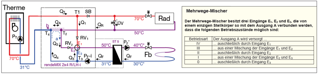
Fig. 3: Therme with dual-circuit system, mixing manifold 2×4 - return utilisation and system separation in the low-temperature circuit - a total of three pumps are required.
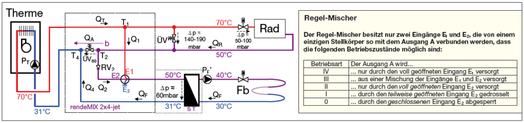
Fig. 4: Therme with dual-circuit system, mixing manifold 2×4-jet - return utilisation and system separation in the low-temperature circuit.
Legend
For this purpose, a differential pressure cartridge was developed that opens from approx. 50 mbar and is fully open at approx. 70 mbar and a flow rate of 1.5 m³/h. This corresponds approximately to a radiator circuit with 35 kW. At the same time, an average pressure loss of 60 mbar even with a residual head of only 200 mbar (=2 mWS) means that for transport
and valve priority, 140 mbar are still available. This has proven to be sufficient. After all, this pair of values (70 mbar; 1.5 m³/h) corresponds to a Kvs value of 5.5 and thus to a commercially available heat exchanger with 30 plates of 200×75 mm². The plate heat exchanger must be dimensioned somewhat larger than the circuit shown in Fig. 2 anyway, since the heat transfer must preferably be managed from the lower return temperature of the high-temperature circuit. However, this investment quickly pays for itself through the higher efficiency and the saved auxiliary energy, especially since it is already financed by the saved pump. Another problem had to be solved: If the multi-way mixer were to open inputs E2 and E3 in operating mode I, the differential pressure would collapse because a pressureless bypass would be opened via T2, E2, E3, T3 and T4. Poor hydraulic decoupling and poor control characteristics would be the result.
The rJET: mixing and control valve in one housing
The solution is to close the wicket E3. As a result, the inputs E1 and E2 continue to act like a mixing valve in operating mode III. In operating mode I, however, input E2 to output A then acts like a control valve. It is therefore possible to maintain both the hydraulic decoupling through constant pressure losses of the differential pressure cartridge in the high-temperature circuit and to realise the optimum flow control of the system separation through a primary-side control valve according to Fig. 1 and Fig. 2. Not only is a circulation pump saved, but the lowest possible return temperature to the heat generator is also achieved, Fig. 4.
Two-zone discharge and return utilisation at the buffer tank increase solar yields and hot water comfort

Fig. 5: Therme with dual-circuit system and combination of dual-zone discharge with return utilisation.
Due to the increasing importance of solar thermal energy, efficient solutions for buffer tanks became more and more important. With the so-called two-zone discharge of a buffer, the multi-way mixer first accesses the hot water of the middle connection before taking hot water from the upper connection. This not only results in a more stable hot zone with greater hot water comfort; the lower part of the buffer also benefits from a larger cold water return and can thus absorb more solar heat. Within the framework of a laboratory experiment, it could be proven that in this way the effectiveness of buffers can be increased by over 30 % with only one heating circuit (cf. IHKS FACH.JOURNAL 2005/06: Series connection of mixed heating circuits increases efficiencies, p.115 and IHKS FACH.JOURNAL 2006/07: Efficiency increase through multi-way mixers, p. 104. Article also under: www.ihks-fachjournal.de/artikel/2006-2007/mehrwege-mischer). A rendeMIX 3×4 now combines this principle with the method of return flow utilisation. Here, the two operating states of the internal switch of the mixing manifold 2×4 described above - water surplus (flow direction b) and water shortage (flow direction a) - are optimised by turning the buffer with its three connections into a hydraulic switch itself: Either colder excess water (flow direction b) or more cold water (flow direction a) enters the lower part of the buffer. From renovation practice, we are often told of savings of up to 50 % through solar heating support. So what could be more obvious than to use the
jet principle of return flow utilisation without pump before system separation to the combination with two-zone discharge, thus creating an optimal solution for the solar renovation market: Comfort and efficiency without additional expenditure on auxiliary energy and installation when using a system separation in the floor circuit!
Optimum solar utilisation with system separation in the low-temperature circuit
The principle of the 2×4-jet, using a differential pressure overflow valve ÜV60 on the one hand and a control mixer on the other, can be transferred to the rendeMIX 3×4. The third connection to the middle buffer connection forms this equalising section. The pump in the boiler drives the heating water through the radiators. The radiator return thus generates a differential pressure that is almost independent of its flow, which allows part of the volume flow to flow through the primary side of the system separation when inlet E2 is open. If the flow temperature in the mixing circuit downstream of the system separation is not sufficient, hot radiator flow is added by opening inlet E1; if the temperature is too high, however, the primary-side flow through the system separation is throttled by closing inlet E2.
The result, in addition to the saved circulating pump, is a
Low return temperature in the lower cold zone of the buffer
and thus a high solar yield and a long hot water service life.
in the upper hot zone of the buffer, Fig. 5.
Author
Dipl.-Ing Hans-Georg Baunach, Managing Director
HG Baunach, Hückhelhoven
Download the technical article as PDF